Building a Corne keyboard
Published on Apr 04

I’ve been lurking around the r/MechanicalKeyboards subreddit for a couple of years which inspired me to go ahead and build a custom keyboard. For the last few years, I’ve been using a Ducky One 2 TKL keyboard which has been a very pleasant experience, but seeing all those cool keyboards really made me curious as to what I could build myself.
After doing some research, I pretty quickly went down the rabbit hole of small ergonomic keyboards. Seeing some of Josean Matrinez’ YouTube video’s, I found the Corne v3. This is a split 40% keyboard, which was completely open source (hey, I see that as a win!) and programmable using QMK. In this post, I’d like to take you with me as I build this keyboard and get some fist impressions of it (as a matter of fact, I’ve written this whole post using the Corne keyboard!).
Hardware
The Corne v3 keyboard has been designed by Foostan, who has provided the keyboard community with all the necessary files to build the keyboard. One of these files is the PCB schematic. A friendly Redditor called Piit79 spent some time and improved this design, after which he put it for sale on his shop called 42Keebs.
Part list
Let’s go over the specific parts I ordered. Most of the things were ordered from the 42Keebs webshop, the other items I ordered from Aliexpress.
- Corne v3 kit with FR4 case from 42Keebs which includes:
- 2x PCB
- 42x SMD diodes
- 42x Kailh hotswap socket
- 2x TRRS socket
- 2x reset switch
- Brass standoffs & screws
- Acrylic covers (for the OLED screens)
- 2x FR4 bottom plate
- 2x FR4 switch plate
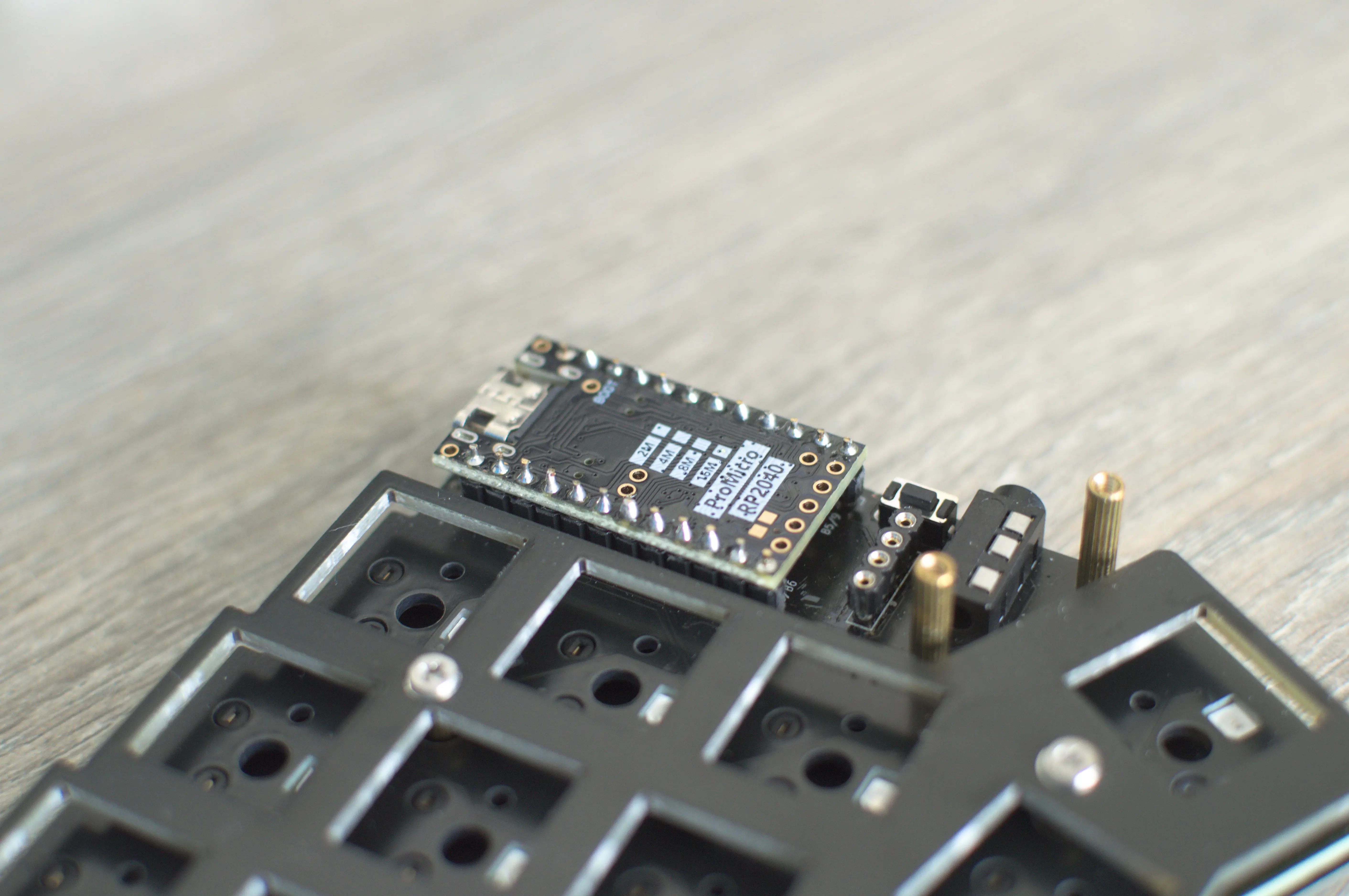
- 2x RP2040 Pro Micro microcontroller from Aliexpress
- 50x pins for Mill-Max socket from Aliexpress
- 5x 40 pin female header from Aliexpress
- 50x Gateron Milky Yellow Pro from Aliexpress
- PBT Keycap set from Aliexpress
- 20x WS2818B 5050 RGB LED from Aliexpress
- 50x SK6812 3535 RGB LED from 42 Keebs.
Putting it all together
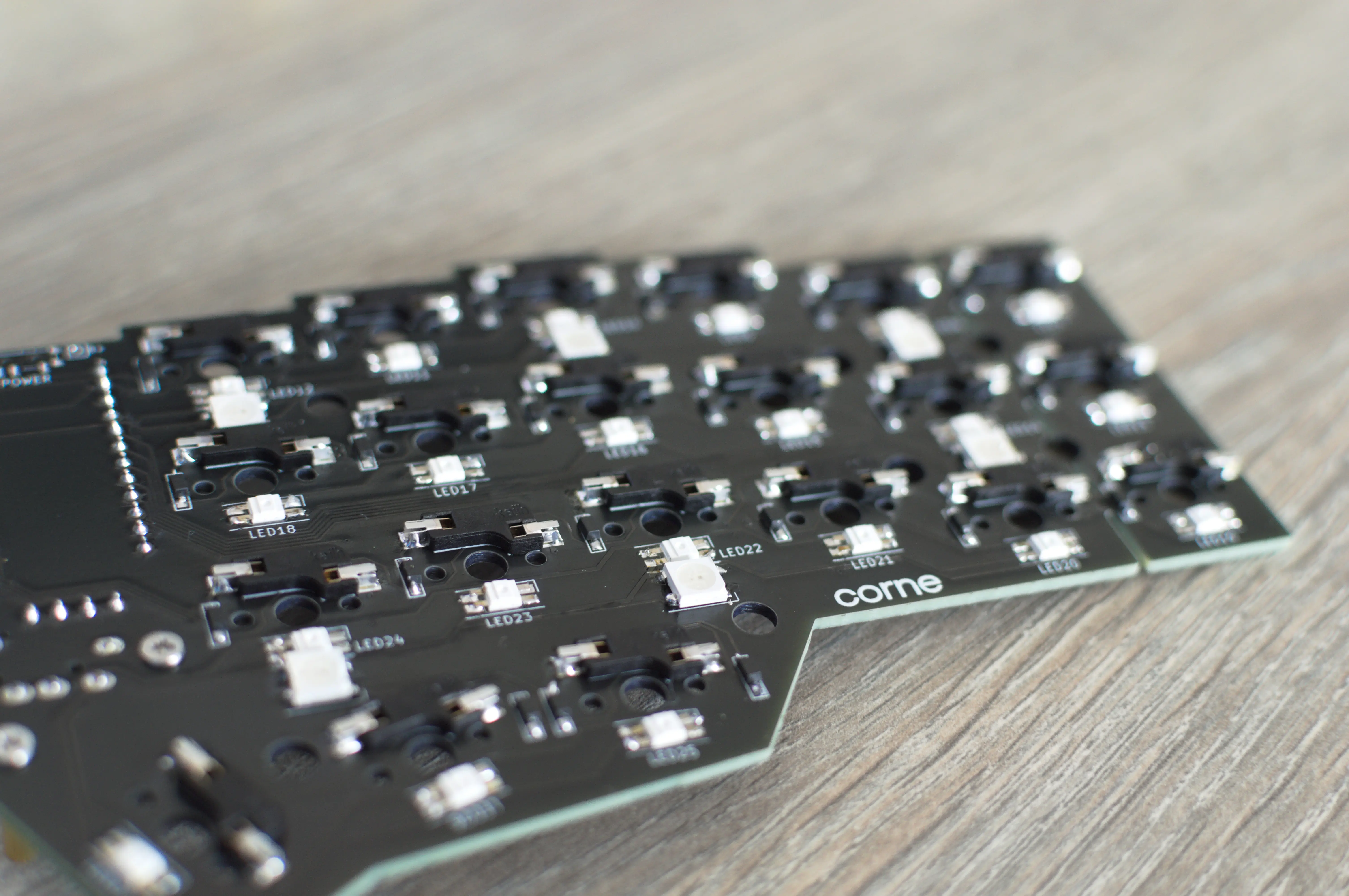
This is where the fun begins, once I had gotten all the parts, it was time to solder them. The first things that I soldered, were the SMD (surface-mounted device) components, which are all the tiny parts (diodes and LEDs). I had read some build logs while I was waiting for the parts to arrive and a lot of them spoke about different soldering iron temperatures but in the end I just used 275 degrees and that worked very well.
Note: when soldering the diodes, first put some tin on one of the two pads, grab your diode, put it on top of the pad and heat the tin. That should secure the diode and allow you to easily solder the other pad. The same thing goes for the LEDs.
Once the SMD components are soldered, you can turn the PCB around and solder on the through-hole components (Mill-Max sockets, reset button and TRRS). These are pretty easy to do, you just might need to tape the Mill-Max sockets down with some painter’s tape to hold them in place.
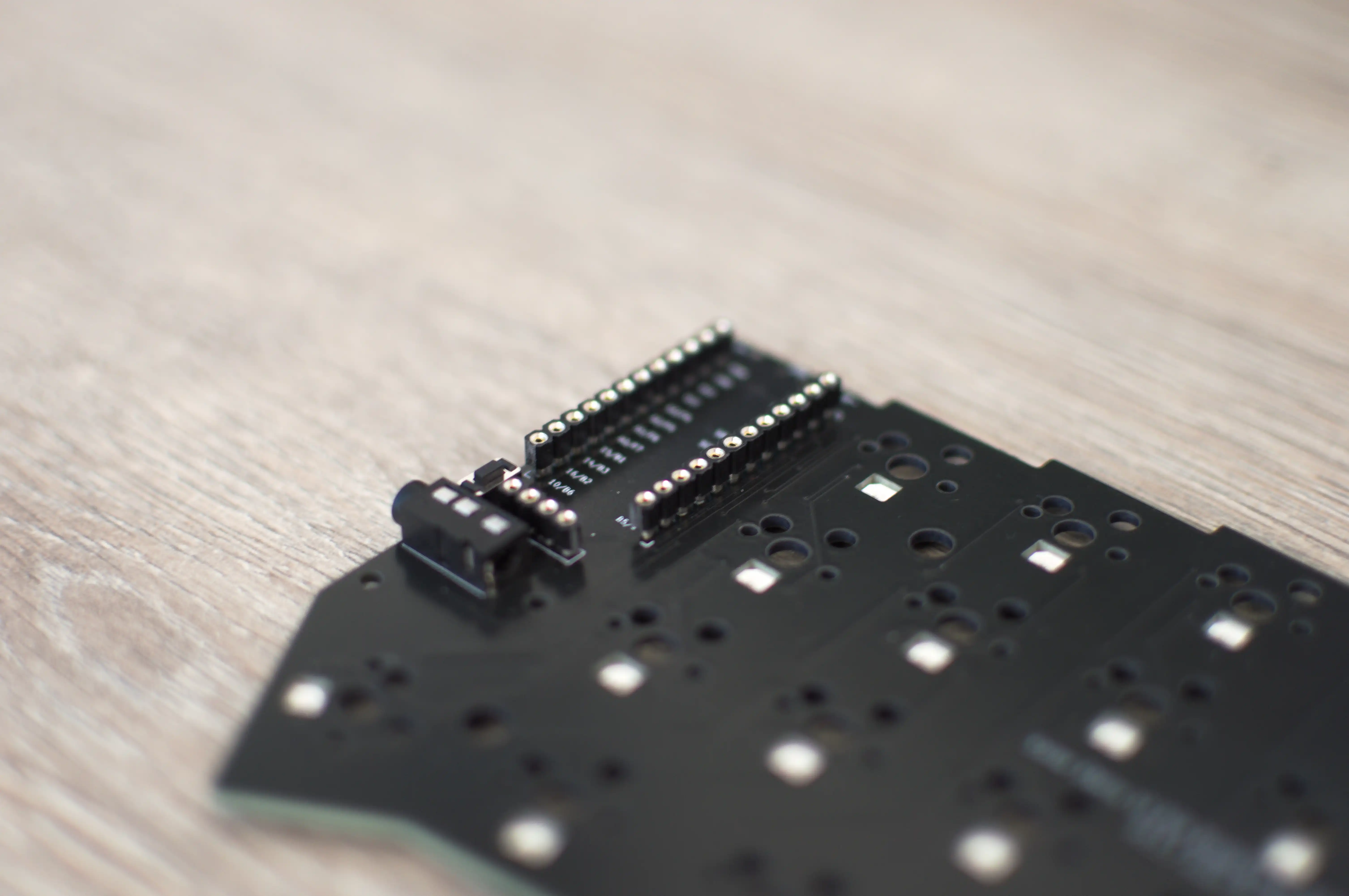
Now that we have the sockets soldered on, we can solder the pins to the microcontrollers. To do this, you can put some painter’s tape on the sockets and push in all the pins. Once the pins are in the sockets, you can insert the microcontroller and solder the pins to the microcontroller.
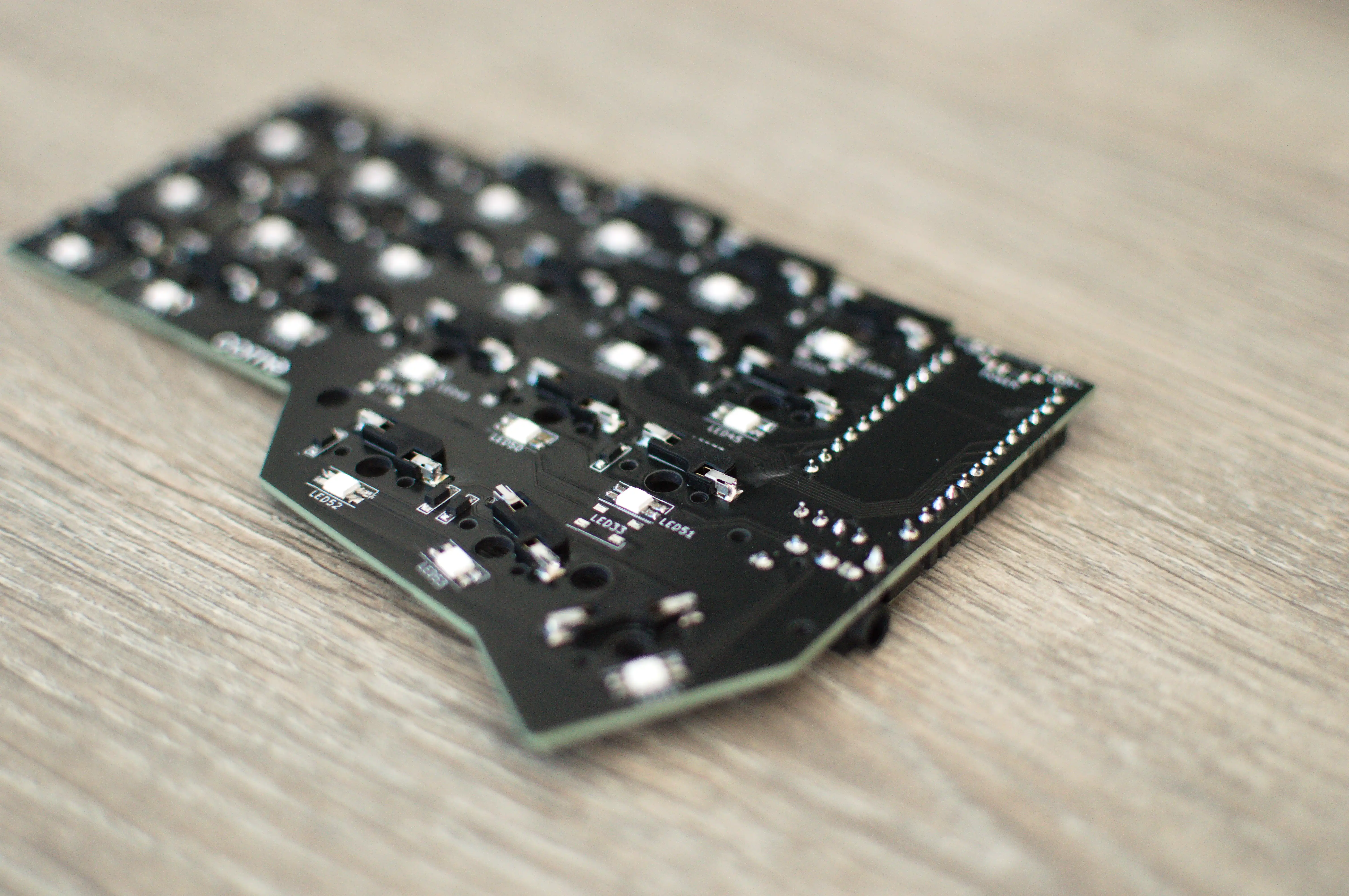
We’re almost through the soldering part (well, for one PCB, I still had to repeat this for the second PCB)! Next up is are the Kailh hotswap sockets. These allow you to easily change the keyboard switches as you just push them into these sockets (instead of soldering them to the PCB). For these, the same way of working applies compared to the diodes and LEDs; put tin (you can put quite some tin on it) on one of the pads on the PCB, hold the socket on top and then heat up the tin.
Note: as you might see, I did not have the underglow LEDs soldered in the picture. I had forgotten about them and soldered them on afterwards. Make sure you have these soldered on before you solder on the Kailh sockets as they make it more difficult.
That should be it for the soldering part, now we just need to assemble the keyboard and we’re good to go. To start, I put a switch in each of the 4 corners of the switch plate.
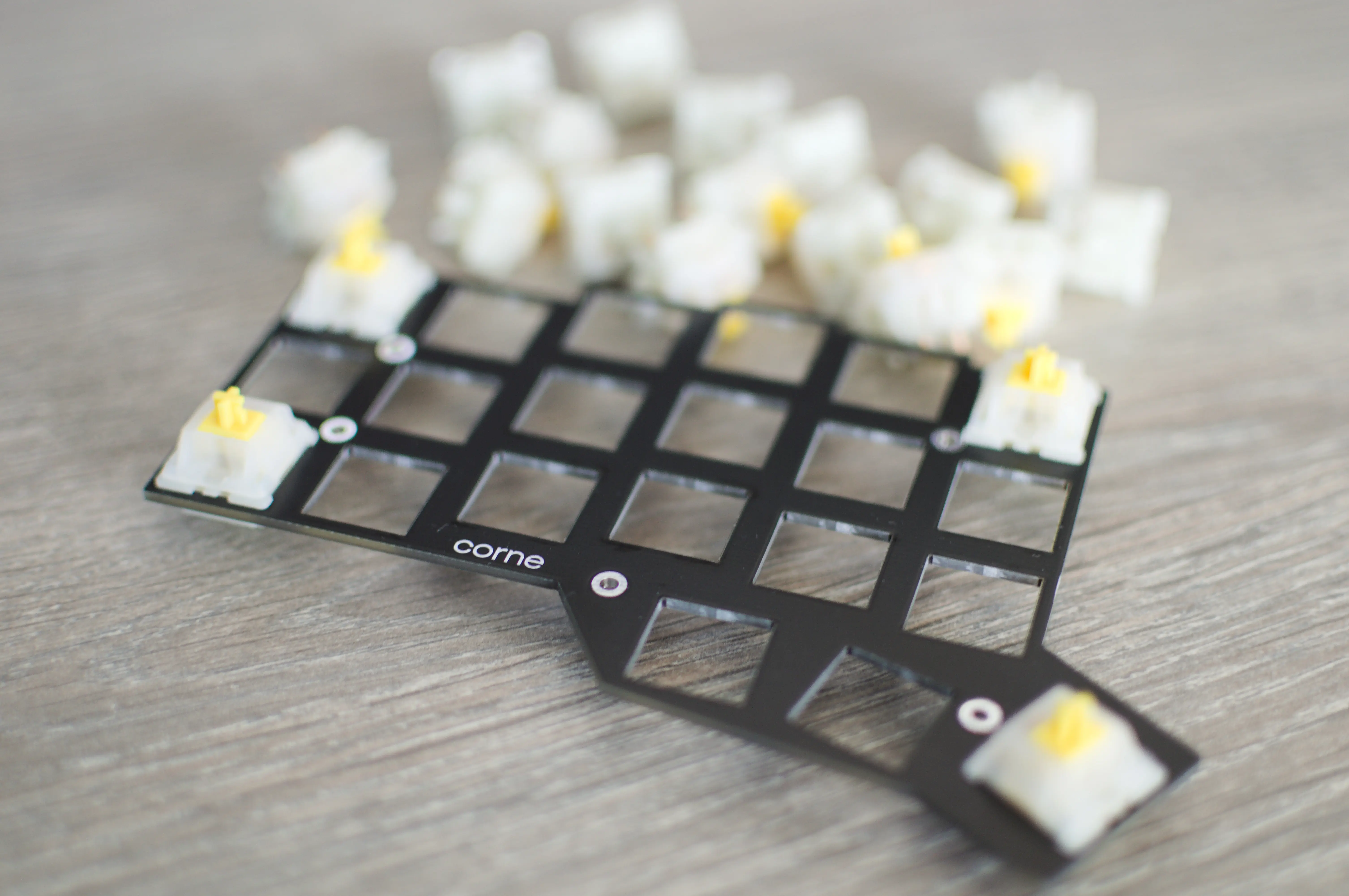
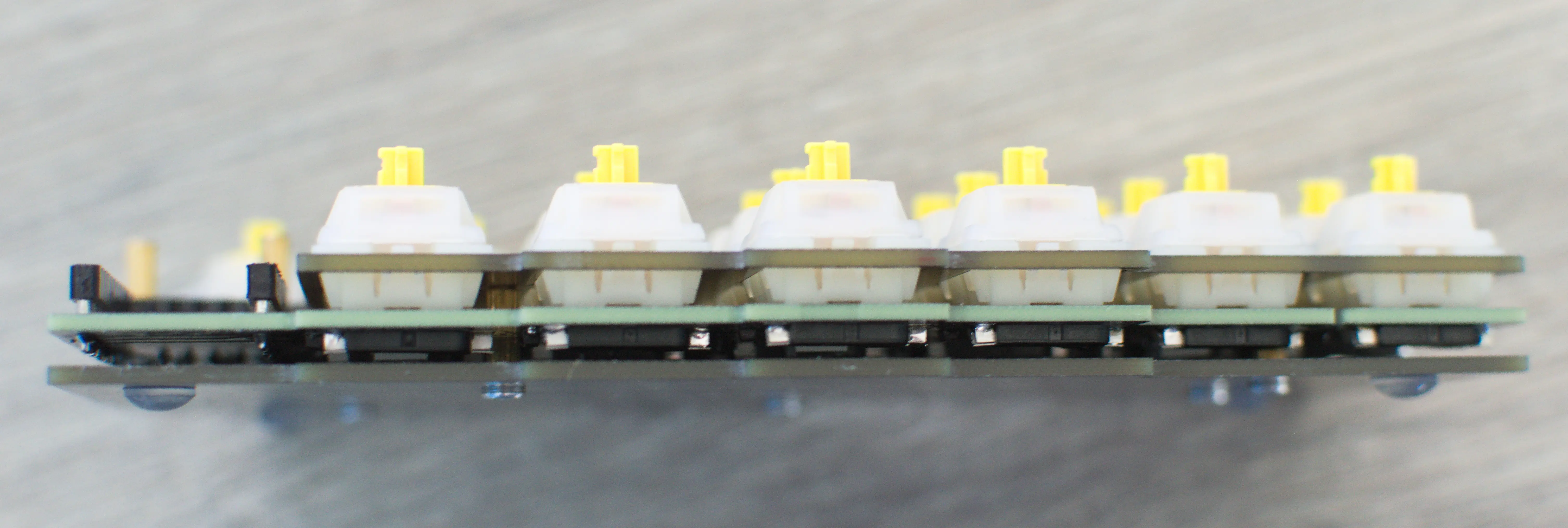
After that, you can push these 4 switches into the Kailh hotswap sockets. These 4 switches should hold the switch plate in place so you can screw the standoffs into the bottom plate, stick them through the holes on the pcb and screw them to the switch plate. Once all of that is done, you can add in all the remaining switches and you should end up with something like this ⬇️.
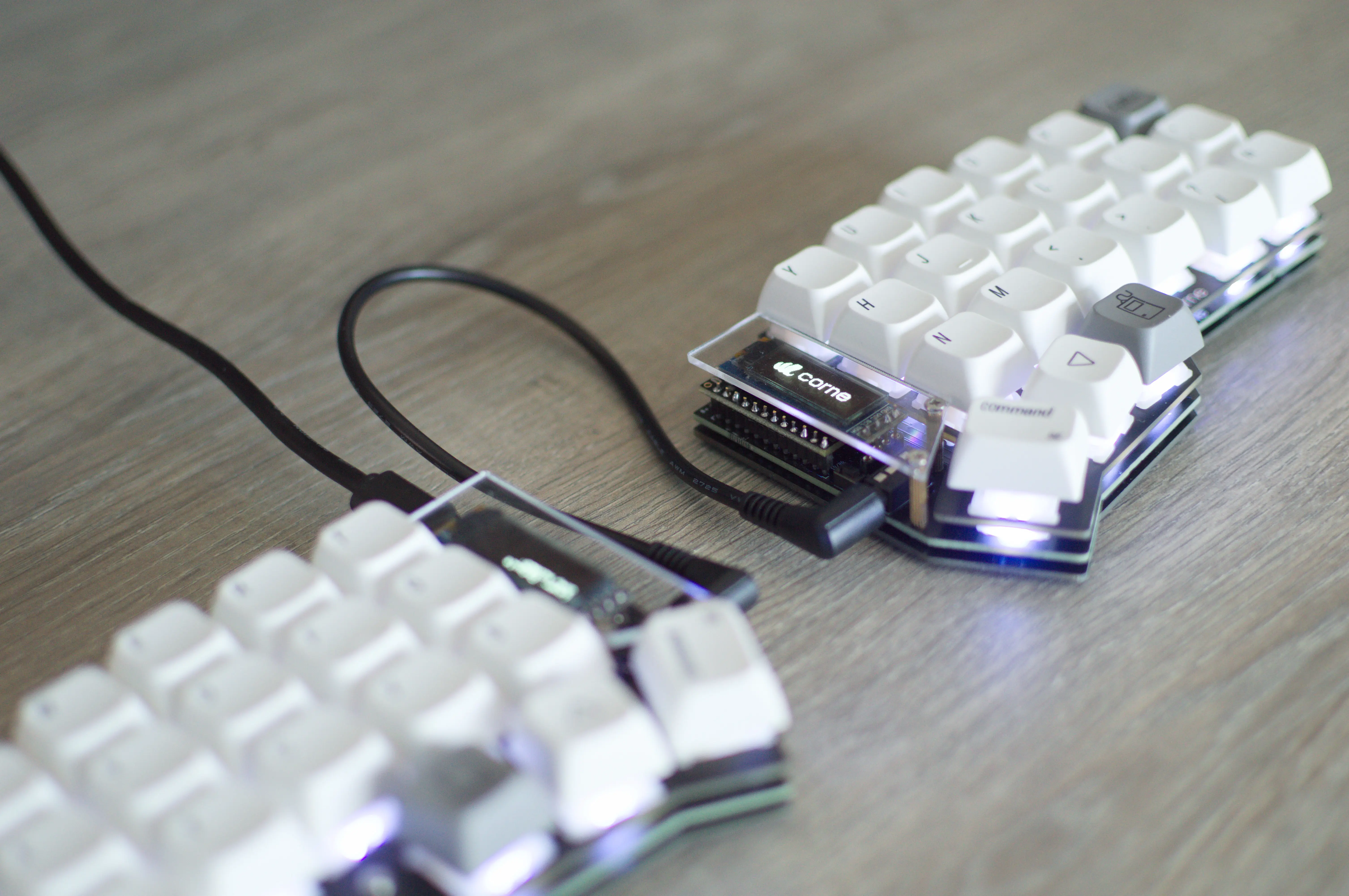
Overview
Adding in the OLED screens, the acrylic OLED covers and keycaps, you should have a fully assembled keyboard. When you plug it into your PC, you shouldn’t see anything special unless you flash it with the default firmware (more on that later) like I did.
Software
Since I’m using RP2040 based microcontrollers, I can use QMK for the software side of this keyboard. If this is your first time hearing about QMK (it was for me); QMK is a popular open-source firmware that can be used to customize and program mechanical keyboards. It has some nice features like key mappings, macro’s, tap dancing,.. which allows a user like me to customize my Corne to my liking.
Writing my own QMK firmware
In order to write my own firmware, I needed to install the QMK CLI by executing the following command python3 -m pip install --user qmk. This CLI tool allows for easy compilation, flashing, keymap generation,..
Once you have the CLI installed, I went ahead and ran the setup function using qmk setup which prepared my development environment by cloning the qmk_firmware repository. From this point, I was able to execute the qmk new-keymap -kb crkbd/rev1 command. This will launch a little wizard that asks you to enter a new keymap name and will create the necessary files for that keymap.
From this, I opened the keymap.c file in the newly created keymap directory and started adjusting it to my liking. To start off, I’m first going to try and get used to a QWERTY layout to shorten the learning curve, but I am planning on switching to Colemak in the future.
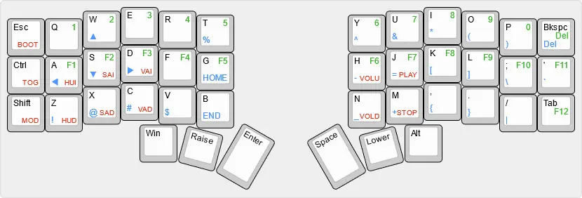
So, going over my personal keymap (I added a little overview above), I have a total of 4 layers which provide me with nearly every key that I need:
- Base layer: used for “normal” typing, includes all the basic keys with some commonly used specials like dot, comma, semicolons, quotes,.. Also has the ESC, CTRL, SHIFT, Backspace and Tab keys.
- Numbers: used for typing numbers and accessing the F keys. Also changes the backspace to a delete.
- Special characters: used for typing special characters like brackets, ampersands, dollar signs,.. Also includes arrow keys for easy navigation.
- Controls: has double functionality, the left is used for controlling the RGB lights (on/off, mode toggle, brightness, hue, saturation). The right side is used for controlling media (play/pause, stop, volume up/down).
One of the next things I am going to do is to add a gaming mode which I can use to play Apex Legends/The Finals/.. with only one half.
Flashing to the keyboard
Once I wrote my firmware, I had to flash it to my keyboard so I could actually use it. Since the Corne is a split keyboard, I need to flash it twice (once for every microcontroller). Luckily, flashing is really easy. I connected one of the two sides of my keyboard to my PC, executed the qmk flash -kb crkbd/rev1 -km vdeborge command, reset my microcontroller by pressing the reset button on my pcb and waited for it to compile and flash. For the second side, I did this a little different because I didn’t want to wait for the whole process again. When you press the reset button, your pc will show the microcontroller as a USB drive. This made it very easy for me to flash it, since I just copied the .uf2 file from the .build folder and pasted it into that USB drive. Once it was copied, the drive went away and my microcontroller was flashed.
Things I’ve noticed
- Don’t disconnect the two halves while the keyboard is plugged in. These TRRS jacks short the pins if disconnected from the keyboard so by disconnecting the cable, you might fry the microcontroller.
- QMK has a lot of features, some of them more useful than others but once I dust off my programming skills, I will have to check out some of them.
- When soldering the components, don’t be scared to put too much soldering tin on them. After putting everything together and flashing the keyboard with my firmware, I had some issues with keys not working and LEDs not lighting up. In the end, I just had to go over my soldering and add some tin in some places.
- Even though it might seem strange at first, a Corne keyboard really does help you with having a more ergonomic typing experience. Looking at how my hands need to move when typing on a normal keyboard versus the Corne, I immediately see that when using my Corne, my hands move a lot less.